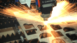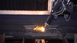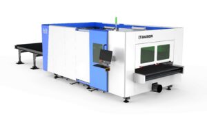
On a busy fabrication floor, operators frequently run into subtle issues that quietly erode throughput and delivery schedules:
A long pipe sags or whips during high-speed rotation, throwing hole alignment off by millimeters. A single test sample passes inspection, yet dimensional tolerances and edge finish drift over a 500-piece production run. Round tubes cut cleanly, but switching to square tubes, rectangular hollow sections (RHS), or C-channels introduces corner burn and contour distortion.
These bottlenecks do more than ruin part geometry—they generate scrap, trigger costly secondary rework, delay shipments, and eat directly into shop margins.
Tube Laser Cutting Quality is not dictated by laser wattage and cutting parameters alone. Chuck Clamping, rotary positioning, dynamic workpiece support, and multi-axis motion synchronization play an equally decisive role in keeping tolerances tight across shifting production loads.
For metal fabricators in structural steel, offshore engineering, agricultural machinery, and HVAC ductwork, the real metric isn’t whether a machine can pierce a single pipe—it’s whether it can sustain Production Consistency across heavy-wall, extra-long, and mixed-profile batch runs.
Below, we break down the seven critical factors governing tube laser cutting performance—and examine how Baison Laser engineers its mechanical architectures to eliminate deflection, hold repeatability, and stabilize high-volume output.
How Baison Laser Solves Stability Bottlenecks in Tube Cutting
Tube sagging, rotational whipping, datum drift, and batch-to-batch variance rarely stem from a single fault. They are systemic issues caused by the interplay between clamping force, support geometry, material feeding, and CNC motion control.
Baison Laser addresses these shop-floor realities through targeted mechanical and automation configurations designed for continuous industrial duty.
1.1 Heavy-Duty Self-Centering Chucks for Rigid Clamping & Rotary Positioning
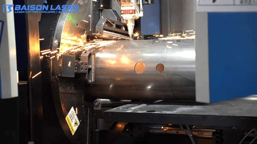
Unlike flatbed sheet cutters, a tube laser relies entirely on its chucks to grip, index, and rotate heavy workpieces during circumferential piercing, slotting, and beveling.
- Enclosed Pneumatic Architecture: Select Baison tube laser series feature fully enclosed heavy-duty chucks with four-jaw paired self-centering mechanics and one-touch pneumatic clamping, eliminating manual jaw adjustments between setups.
- High-Rigidity Bearings: Built-in cross-roller bearings within the rotary drive unit ensure smooth, zero-backlash rotational indexing.
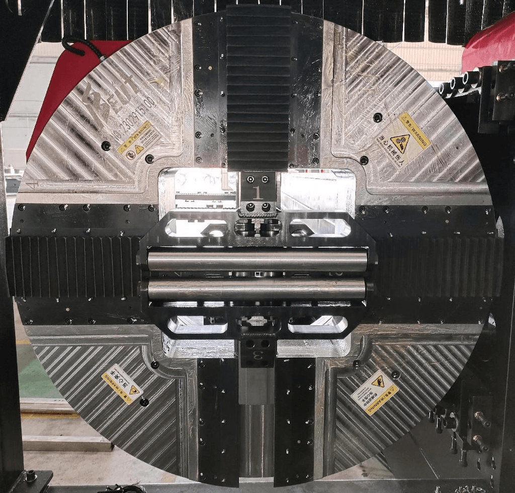
- Verified Positioning Accuracy: Depending on the machine series, positioning Repeatability reaches ± 0.03 mm to ± 0.05 mm. (Note: This metric reflects the machine’s mechanical positioning repeatability, which differs from final part cutting tolerances influenced by material stress and thermal input).
- Full-Stroke Chuck Options: Available full-stroke chucks accommodate varying tube diameters without manual jaw swaps, drastically cutting changeover downtime in high-mix job shops.
1.2 Servo Follow-up Support to Eliminate Long-Tube Deflection
As long tubes feed and spin, gravity and centrifugal inertia cause mid-span sagging, harmonic vibration, and lateral whip.
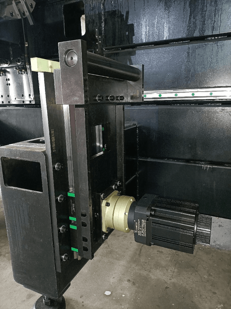
To counteract this, select Baison models come standard with Servo Follow-up Support. These CNC-synchronized support rollers actively track the cutting zone and adjust height dynamically, cradling the tube throughout rotation to prevent datum shift. The servo support assembly operates independently of the loading rack, allowing shops to configure material handling based on floor layout.
1.3 Travelling 3-Chuck System for Extra-Long, Heavy-Wall Profiles
For extreme lengths and heavy-wall, large-diameter structural tubes, Baison offers an optional Travelling 3-Chuck System.
Engineered specifically for dynamic load distribution during continuous feeding, three coordinated chucks move synchronously to provide multi-point clamping directly ahead of and behind the cutting head. (We detail the exact kinematics and application thresholds of this system in Section 3).
1.4 Automated Material Handling for Uninterrupted Batch Runs
In high-volume environments, feeding bottlenecks limit machine utilization just as much as cutting speed.
Baison’s optional Automatic Loading System pairs with pneumatic support stages to deliver continuous, hands-free tube feeding:
- Anti-Tangle Separation: Square divider blocks isolate individual tubes in the staging zone, preventing nested bundles from jamming or scratching during singulation across round, square, and rectangular profiles.
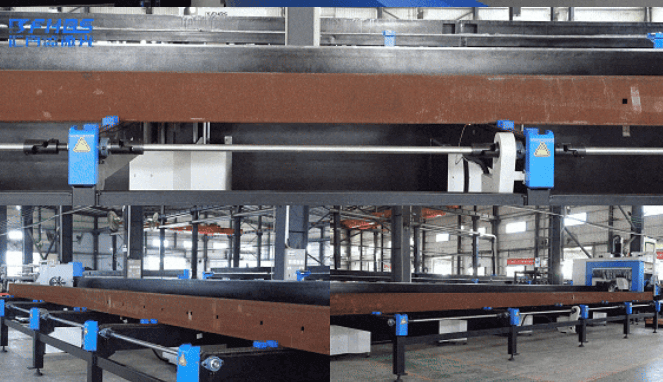
- Shop-Floor Logistics Ready: Open overhead clearance accommodates both forklift and overhead crane loading, letting operators stage heavy bundles according to existing shop material-handling workflows.
Evaluating whether automation fits your shift volume? Read our ROI breakdown on whether a tube laser automatic loader is worth the extra cost to calculate labor savings and payback periods.
The 7 Core Factors Driving Tube Laser Cutting Quality
Every cut edge and hole tolerance is governed by two interconnected domains: laser process physics (how thermal energy melts and evacuates metal) and mechanical kinematics (how rigidly the machine holds and moves the workpiece along the programmed toolpath).
2.1 Laser Power & Beam Quality
Laser wattage determines raw thermal energy input, yet higher power does not automatically equal better cut quality.
- Thermal Balance: Insufficient power leaves incomplete cuts and stubborn bottom dross. Conversely, excessive power paired with slow feed rates widens the kerf, over-melts edges, and expands the heat-affected zone (HAZ).
- Beam Parameter Product (BPP): Superior beam quality and uniform energy density produce narrow, parallel kerf walls and cleaner molten metal ejection.
- Application Matching: Rather than chasing maximum wattage, parameters must be dialed in to match wall thickness, alloy reflectivity, and corner geometry.
2.2 Focal Position
The focal point dictates where laser energy concentrates relative to the material’s top and bottom surfaces, directly shaping kerf taper and edge roughness.
- Cut Edge Geometry: An improper focal offset causes uneven top-to-bottom kerf width, heavy striations, and underside burrs.
- Profile-Specific Compensation: On round pipes, focal distance remains constant. On square tubes, rectangular sections, and structural channels, the relative angle and standoff distance change as the cutting head transitions across flat faces, rounded corners, and sharp edges—requiring dynamic focal and height control.
2.3 Cutting Speed & Synchronized Process Parameters
Feed speed must stay locked in equilibrium with laser power, wall thickness, focal depth, and assist gas pressure.
- Speed Mismatches: Moving too fast starves the cut front of energy, causing discontinuous cuts; moving too slow dumps excess heat into the part, triggering edge melt and thermal warping.
- Trajectory-Aware Modulation: Tube processing involves tight arcs, small-diameter holes, slots, and sharp 90-degree corners. The CNC controller must dynamically ramp laser power and gas pressure down during corner deceleration to prevent localized blowouts.
2.4 Assist Gas Selection & Delivery Stability
Assist gas clears molten slag from the kerf while driving exothermic reactions (in oxygen cutting) or shielding the edge from oxidation (in nitrogen/air cutting).
- Critical Variables: Gas type, purity, nozzle pressure, and flow rate directly control edge cleanliness.
- Preventive Maintenance: Drop-offs in line pressure or a damaged, off-center nozzle leave molten dross welded to the bottom edge. Regular checks of gas regulators, lines, and nozzle concentricity are non-negotiable for shift-to-shift consistency.
2.5 Chuck Clamping & Rotational Positioning
Because the workpiece rotates beneath the cutting head, chuck integrity is the primary mechanical driver of hole-to-hole and wrap-around accuracy.
- The Cost of Slippage: Any micro-slippage during rapid rotational acceleration—or backlash in the rotary drive—immediately translates into skewed hole patterns, distorted saddle cuts, and out-of-tolerance part lengths.
- Mechanical Protection: Fully enclosed heavy-duty chucks shield internal gears and cross-roller bearings from abrasive metal dust and slag, preserving clamping force and rotational smoothness over years of operation.
2.6 Workpiece Support & Multi-Axis Motion Synchronization
Tube length, deadweight, and cross-sectional stiffness dictate how much support is needed to prevent deflection.
- Static vs. Dynamic Deflection: Unsupported long tubes droop under their own weight and whip laterally during high-RPM indexing, altering the true standoff distance between the nozzle and tube surface.
- Closed-Loop Coordination: High-precision tube cutting requires Servo Follow-up Support (or multi-chuck tracking for heavy loads) working in tight synchronization with X-axis feeding, chuck rotation, and cutting head motion. Even slight lag between axes will distort complex 3D bevels and intersecting joint profiles.
If your shop processes heavy structural joints that require weld preparation, explore how laser bevel cutting for structural steel and heavy equipment eliminates secondary grinding and milling.
2.7 Material Properties & Cross-Sectional Geometry
Raw stock characteristics introduce real-world variables that ideal CAD models never show:
| Profile Type | Common Industrial Applications | Primary Cutting & Clamping Challenges |
| Round Tubes | Mechanical components, furniture, fluid lines | High-speed rotational indexing; circumferential hole alignment |
| Square & Rectangular Tubes | Structural frames, machine bases, racking | Corner radius transition; thermal buildup on sharp edges |
| Oval & Special Profiles | Architectural structures, custom equipment | Irregular clamping geometry; complex 3D toolpath compensation |
| Structural Channels (C, L, H) | Heavy steel construction, agricultural chassis | Off-center gravity; specialized jaw grip and web-to-flange clearance |
Note: Not every tube laser can process all structural profiles—actual capability depends on chuck jaw geometry, support carriage range, and dedicated CNC nesting/beveling software. Furthermore, surface rust, mill scale, oil residue, and raw stock straightness tolerances will directly impact cut stability.

What Makes Baison’s Travelling 3-Chuck System Different?
When cutting extra-long, heavy-wall structural pipes, extreme deadweight and rotational inertia overwhelm standard two-chuck layouts.
A conventional Fixed Three-Chuck System places three chucks at stationary points along the machine bed. While effective for standard applications, stationary chucks cannot adapt their support spacing as a 12-meter pipe feeds forward, leaving long cantilevered overhangs unsupported near the end of the cut.
Baison Laser’s Travelling 3-Chuck System solves this by enabling the chucks to translate along the bed in sync with material feed. Three chucks dynamically clamp and travel together, maintaining continuous, multi-point support directly straddling the cutting zone from the first pierce to the final tailing cut.
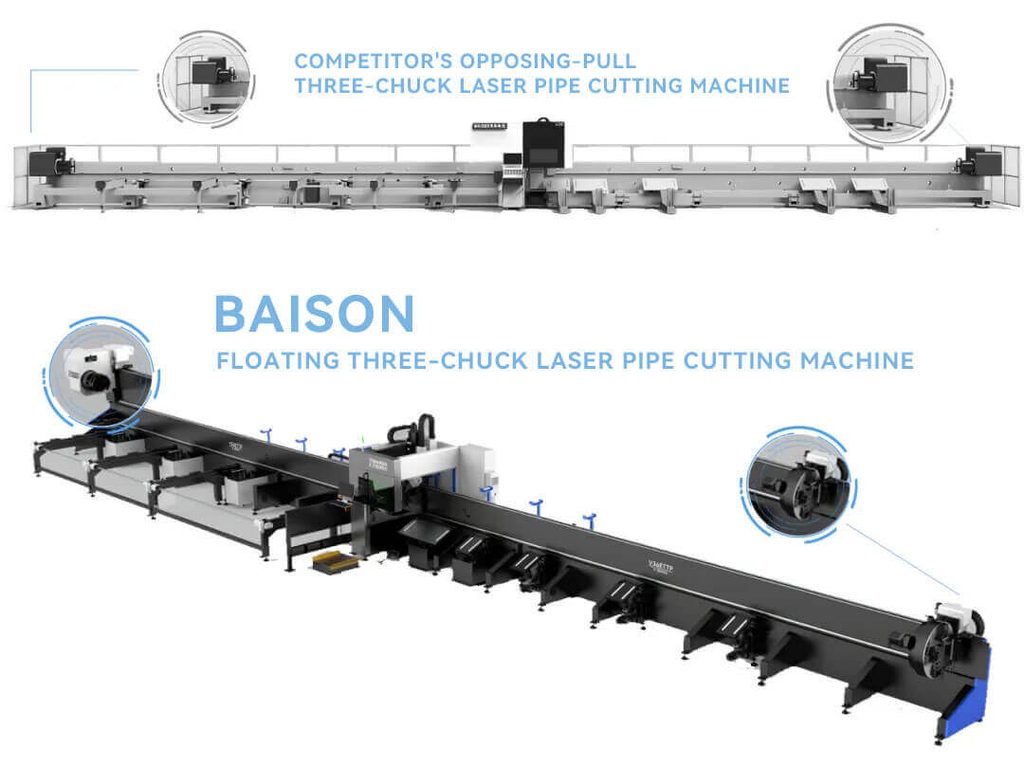
Core Operational Advantages:
- Multi-Point Load Distribution: Eliminates mid-span sag and lateral whipping on heavy-wall pipes.
- Dynamic Feed Tracking: Chucks reposition on the fly to keep clamping points optimal throughout the entire feed stroke.
- Synchronized Multi-Axis Kinematics: Seamlessly coordinates chuck translation, high-torque rotation, and cutting head motion for complex structural joints.
Engineering Note on Configuration Selection: The Travelling 3-Chuck System is a specialized optional architecture—not every shop needs it. For standard tube lengths and wall thicknesses, a two-chuck machine paired with Servo Follow-up Support delivers optimal ROI. (See our comparison on why you shouldn’t blindly overpay for a 3-chuck laser cutter when a heavy-duty dual-chuck system covers your tolerances).
However, if your shop routinely processes extra-long, large-diameter, or heavy-wall tubes, evaluating a travelling three-chuck setup is critical before finalizing your capital equipment spec. (Not sure which chuck configuration fits your exact weight-per-meter load? Our application engineers can run a mechanical load check on your drawings—see below).
For a deeper look at how this architecture performs on 12-meter marine and offshore pipes, see our engineering breakdown on solving 12m pipe sagging, vibration, and tailing waste with heavy-duty tube lasers.
How to Evaluate Accuracy & Production Consistency Before Buying a Tube Laser
Never judge a tube laser solely by peak wattage, rapid traverse specs, or a single showcase sample cut in a showroom. For production fabricators, the only metric that matters is sustained dimensional repeatability across full shift runs.
Use this five-point verification checklist during machine trials:
- Test With Your Actual Production Stock: Bring your everyday alloys, wall thicknesses, diameters, and structural profiles. If you cut square tubes and C-channels alongside round pipes, test every profile—not just an easy thin-wall round sample.
- Inspect Cut Edge Perpendicularity & Dross: Examine kerf smoothness, burr formation, and slag adhesion. Verify overall part length, hole diameters, hole-to-hole pitch, and saddle contours against your GD&T callouts. On thick-wall tubes, check cut-face perpendicularity carefully.
- Run Complex 3D Contours & Profile Transitions: Test real production features—intersecting fish-mouth joints, slotted tabs, miter bevels, and corner wrap-arounds on rectangular tubing—to verify kinematic synchronization across profile faces.
- Audit Multi-Stage Batch Consistency: This is the ultimate stress test. Cut a continuous batch of identical parts from the same material lot, then inspect samples pulled from the start, middle, and end of the run:
- Does overall cut length stay locked within tolerance?
- Do hole diameters and datum positions drift as components warm up?
- Does edge finish remain identical from part #1 to part #100?
- Remember: True Production Consistency cannot be inferred from a positioning repeatability spec sheet alone—it must be proven under continuous thermal and mechanical load.
- Evaluate Chuck, Support & Automation Integration: For heavy, long, or high-mix production, verify how smoothly the chucks, follow-up supports, and Automatic Loading System hand off material without bottlenecks or surface marking.
For a complete specification checklist covering wattage matching, chuck bore sizing, and payback modeling, consult our Heavy Duty Laser Pipe Cutter Selection Guide.
FAQ: Tube Laser Cutting Quality & Equipment Selection
Q1: What are the primary factors affecting tube laser cutting quality?
A: Cut quality is determined by two sets of factors: laser process parameters (laser power, beam quality, focal position, cutting speed, and assist gas pressure/purity) and mechanical stability (chuck clamping force, rotational positioning, dynamic workpiece support, and multi-axis motion control). Material metallurgy, wall thickness, and profile cross-section also dictate parameter setup.
Q2: Why do hole positions drift when laser cutting long pipes?
A: Long pipes carry significant deadweight. Without adequate dynamic support, gravity and centrifugal force cause mid-span sagging, lateral whip, and harmonic vibration—shifting the pipe relative to the cutting nozzle. Chuck slippage, rotary backlash, and axis desynchronization also cause hole drift. Solving this requires evaluating both your support system (e.g., Servo Follow-up Support) and chuck rigidity.
Q3: What causes heavy burrs or dross on laser-cut tubes?
A: Dross and burrs typically point to an imbalance between laser power, feed speed, focal position, assist gas pressure, or nozzle condition (such as a worn or off-center orifice). Because alloy composition and wall thickness alter melt viscosity, parameters must be tuned specifically for each material grade—if you are fighting persistent dross on a specific alloy, sharing your material grade and wall thickness with our process team can help pinpoint the exact parameter bottleneck.
Q4: How does Baison’s Travelling 3-Chuck System differ from a Fixed Three-Chuck System?
A: The key difference lies in chuck mobility. A Fixed Three-Chuck System holds chucks in stationary positions along the bed, which leaves long overhangs unsupported during extended feeds. Baison’s Travelling 3-Chuck System moves all three chucks synchronously with the tube feed, maintaining multi-point clamping directly ahead of and behind the cutting head to eliminate sag and dimensional drift on extra-long, heavy-wall tubes.
Q5: Can one tube laser cutting machine process round tubes, square tubes, and C-channels?
A: Select models handle round, square, rectangular, oval, and structural profiles (such as C-channels and angle iron), but exact compatibility depends on chuck jaw design, support carriage geometry, and CNC nesting/cutting software. Always send your exact cross-sectional dimensions and drawings for engineering verification before purchasing.
Q6: How can I verify a tube laser’s batch production consistency before buying?
A: Request a continuous multi-piece test run using a single batch of your actual production material and part drawings. Measure critical dimensions—overall length, hole pitch, contour accuracy, and edge roughness—on samples pulled from the beginning, middle, and end of the run. Comparing results across all three stages reveals true thermal and mechanical stability. (Want to run this exact three-stage audit on your toughest part drawing? See how to schedule a live test below).
Request a Custom Sample Cutting Test
Choosing the right tube laser cutting machine goes far beyond comparing kilowatt ratings and rapid traverse speeds. Real shop-floor profitability comes down to sustained clamping rigidity, dynamic workpiece support, and multi-axis repeatability across every shift.
Through our full lineup of tube laser cutting systems—engineered with heavy-duty self-centering chucks, Servo Follow-up Support, optional Travelling 3-Chuck architectures, and Automatic Loading Systems—Baison Laser helps metal fabricators master complex profiles, extra-long pipes, and heavy structural steel.
Ready to validate cut quality on your own parts? Submit your material grade, tube dimensions, wall thickness, and CAD/DXF part drawings to Baison Laser. Our application engineers will evaluate the optimal machine configuration for your workload and run a dedicated Sample Cutting Test—giving you physical parts and inspection data to verify edge finish, dimensional accuracy, and batch consistency before you invest.
[Submit Your Tube Specs & Drawings for a Free Sample Cutting Test ]